Saw Cutting Recommendations (Speeds & Feeds)

These are general cutting speed recommendations, and may vary from application to application. Martindale/Gaylee does not assume any liability in the following recommendations, which are basically suggestions on where to start. Please contact us if you have questions.
- Materials list from Machining Data Handbook-3rd Edition, published by the Machinability Data Center. For specific metals/materials within each material category, refer to Machining Data Handbook
- Hardness range listed in Brinell unless otherwise noted. ‘Range’ covers all metals/materials listed within each material group. Reduce speed for harder and more abrasive materials, and for deep cuts. Increase speed for free-machining and non-ferrous metals.
- Thermosetting plastics have various hardness scales. Refer to Machining Data Handbook
(in. per tooth - IPT or chip load per tooth - CLPT)
(in. per tooth - IPT or chip load per tooth - CLPT)
NOTE: This is a conservative recommendation as a starting point for feed rates, and may vary depending on material being cut and cutting speed (SFPM).
If a saw is working well, send it to us and we will duplicate it.
If a saw is not working well, send us a used blade. We can sometimes make recommendations from wear marks on the saw.
Variations to number of teeth, rake angle, clearance angle, bevel, side clearance, material, land, etc. may improve performance and tool life.
- Deep cuts and soft material require fewer teeth (for chip clearance) and stronger teeth (landed).
- Thin material requires more teeth (at least 2 teeth engaged in cut).
- Hard materials and narrow slots (under .025”) likewise require more teeth.
- Alternately beveled teeth keep chips from sticking in the cut and in the tooth gullets.
- Rake Angle: On center for iron and steel, 5° negative for yellow brass, from 5° to 10° positive for other soft materials.
- There should be at least 2 teeth engaged in the cut
- Increase Number of Teeth For:
-
- – Thin material
- – Thin cuts (under .025”)
- – Slow spindle speeds
- – Hard material
- – Sandy castings
- – Thin castings
- – Work hardened
- – Hard spots
- Decrease Number of Teeth For:
- – Chip clearance and tooth strength (Consider Metal Slitting or Copper Slitting style saws.)
- – Deep cuts (over 1/4”)
- – High speeds
- – Free cutting material
- Also known as dish or hollow grind
- Increase for stainless steel and tenacious metals such as copper, zinc, tin or lead.
- Breakage / Wobble / Rubbing: These problems may be caused by how washers are mounted on either side of saw.
- Washers drive saws in absence of a driving key, and must always be clean, flat and bur-free. A speck of dirt will let saws wobble and cut oversize. If a saw breaks, it may score washers. Check marks around saw hole for: dirt; shiny spots (as small as a pinpoint, indicating chips imbedded under washers); and circular skid marks, which indicate nut is not tight.
- Thin saws should especially be supported by washers as large as possible.
- Washers must be of equal diameter or they will flex out saw dish and cause one side of saw to rub.
- Nut must be wrench-tight.
- If saw blade pauses momentarily in its rotation while feed advances, it will break.
- In addition to causes noted under “MOUNTING OF SAWS”, teeth may break when starting a cut at too fast a feed, if spindle bearings are worn, drive belts loose or sheaves worn, workpiece indexed before saw has cleared slot, improper workholding (workpiece not tight or not well supported), or saw is dull (even the best eventually wear out).
- Vibration and chatter may have many causes, including the following:
-
- -Arbor bent or worn undersize
- – Workpiece improperly supported, particularly with thin material
- – Teeth too coarse/fine
- – Speed too slow / too fast
- – Dull tool
- – Wrong clearance angles
- – Feed too slow
- – Climb milling recommended on CNC equipment. Conventional milling preferred on manual equipment, but climb milling may help to keep small parts from being ripped from the clamping fixture. It may also reduce burs.
- Seizing: not enough coolant in cut
- Not enough side clearance
- Cutter speed too fast and/or feed too slow. The work may glaze and the saw will rub.
- Coolant helps keep saw and workpiece cool for optimum cutting conditions. Please contact your coolant supplier for recommendations.
- Cold jet airstream often used for dry cutting operations to clear chips and keep saw and workpiece cool.
- When resharpening saws, all wear marks must be removed from teeth. If wear is excessive, we will regrind diameter below wear marks. Either way, thickness is reduced because of side clearance required for even shallowest cuts.
- Carbide tipped saw blades can be retipped and ground to original specifications.
Cutting tool surface coatings are available upon request. Tool coatingsprovide tool wear resistance while significantly improving theperformance of saws in most applications, particularly when cuttingferrous materials. These coatings are extremely thin, harder than steeland greatly reduce friction and wear. The most common coatingsavailable for Martindale/Gaylee Saws are:
- TiN: Titanium Nitride - General purpose TiN hard coating. Best suited for iron-based materials, unalloyed and alloyed steels and hardened steels.
- TiCN: Titanium Carbonitride - Enhanced hardness and wear resistance over TiN with better surface lubricity. Suited for difficult to machine materials such as cast iron, aluminum alloys, tool steels, copper, Inconel, titanium alloys and nonferrous materials.
- TiAlN: Titanium Aluminum Nitride - Nano-layered coating, high toughness and oxidation resistance. Recommended for high temperature cutting, and a good choice when coating carbide. Suited for difficult materials like cast iron, aluminum alloys, tool steels and nickel alloys.
- AlCrN: Aluminum Chromium Nitride - Expanded performance capabilities over titanium-based coatings. Highest oxidation resistance and hot hardness for high temperature wear resistance. Can be used in wet/dry cutting applications. Well suited for a wide range of materials - cast iron, unalloyed steels, high strength steels, high hardness steels.
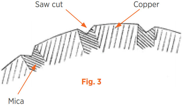
Once commutator has been resurfaced, mica insulation separating copper segments must be undercut. Undercutting is most easily accomplished with armature removed from machine. However, various tools are available to undercut commutator “in place”.
After undercutting, commutator must be carefully inspected to assure all copper particles removed, all bars chamfered, and all sharp edges and burs eliminated. Slots should be individually checked and reworked to remove any traces of fin or side mica.
Commutator surface should then be lightly polished with fine-grain commutator stone or rubber bond cleaning stone to properly finish commutator surface.
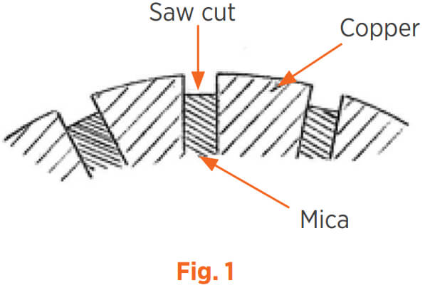
Three basic types of slots may be produced by circular cutters: U-slot, V-slot, and compound land slot.
U-slots (Fig. 1) are generally preferred if slots are accessible for easy cleaning. If cut carefully, these slots are effective until commutator has worn down full depth of undercut. Slot should be cut 1/32”-3/64” (.031-.046) deep, or to OEM specifications. If slot cut too deep, accumulated dust will not be thrown out by the centrifugal action of the rotating commutator.
Choose cutter width to slightly exceed mica thickness (recommend +.003” / .08mm). This allows saw to remove full width of mica plus .0015” (.04mm) copper on each side of slot. If unable to determine mica width, a feeler gage may help determine required saw thickness.
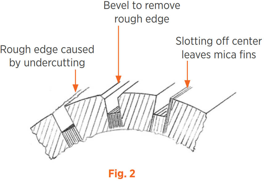
Undercutting may leave a bur (see Fig. 2). Edge of bar might become work hardened, leading to nonuniform wear and possible damage to brushes. Edges of bars must be chamfered to remove bur and work hardened area through use of suitable slotting file or specialty scraper. A chamfer of 1/64” (.4mm) is usually adequate. See Hand Tools section of catalog for slotting files and chamfering tools.
For best results, go over commutator a second time with a V-cutter to simultaneously chamfer both edges of slot.
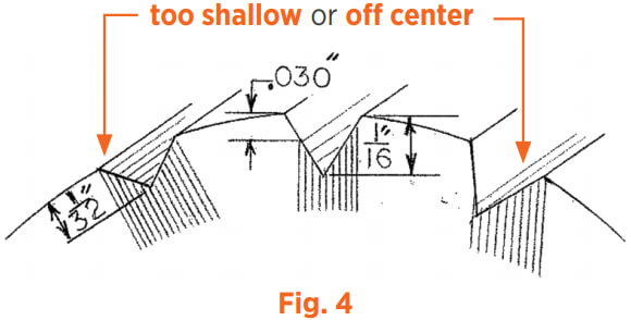
V-slots keep slots free from dust accumulations at low speeds, and do not require a separate operation for chamfering of bar edges. V-slots are usually made with either a slotting file, or a “V” tooth circular cutter. Usual practice is to use a circular cutter having an included angle between cutting edges such that a cut made 1/16” (1.6mm) deep will also leave 1/32” (.8mm) free copper above the mica. Standard V-cutters are available with 40°, 50°, or 60° angles between cutting edges.
Use following table to obtain 1/16” (1.6mm) deep cut with 1/32” (.8mm) free copper above mica:
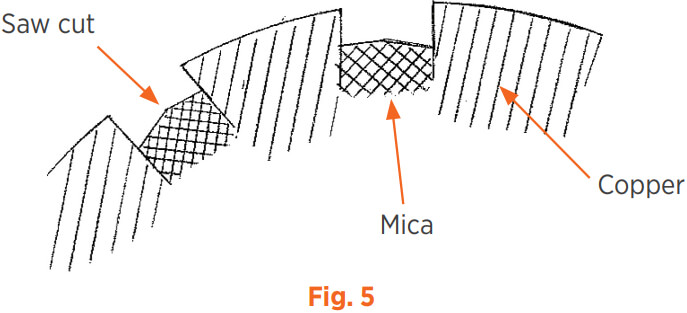
Circular cutter must be accurately centered on mica (see Fig. 4). When cutter is not accurately centered, wedge-shaped mica fins in V-slots are more difficult to remove than fins with uniform thickness left after U-slot.
Mica fins are left in slots that are:
Teeth on compound land mica saws are alternately ground to a special taper which reduces impact on each individual tooth and produces chips just slightly over half of slot width. This eliminates chips’ tendency to clog slot. Saw will operate cooler and clear chips better, prolonging saw life.
When undercutting with compound land saws, bottom of slot will appear flat. However, as a result of reverse taper on alternate teeth, slot bottom will have slight pyramid or convex profile.